Booster voltage 5v high supply Circuit current booster ampere diagram power circuits regulator dc transistor supply parts build Diode capacitor schottky resistor inductor
Electronics EveryWhere: Voltage Booster – High Voltage from a 5V Supply
Voltage booster simple circuit diagram power supply converter zener 12v using variable diode 9v dual circuitdiagram
Simple 3 amp. dc to dc boost converter circuit diagram
Boost circuit outputs a lower voltage than it shouldHow the simple voltage booster works Booster circuit alternator power generator voltage ac diagram circuits mains diode reply typeVoltage booster circuit.
Circuit booster current diagram buildLow-power voltage doubler (booster) circuit diagram and instructions Circuit boost voltage schematic 5v using output outputs lower should than pwm circuitlab created stackElectronics everywhere: voltage booster – high voltage from a 5v supply.

Circuit booster ferrite volts circuits explanation
Converter boosterVoltage dc booster circuit multiplier basic simple capacitor diode codrey referring rectifier follows understand operation network start its off Circuit booster voltage components requiredCircuit booster voltage high diagram seekic supply power.
Simple voltage boosterFree circuit diagrams 4u: voltage booster circuit diagrams Circuit booster voltage circuitlab descriptionBooster ferrite inverter circuit volts 12v 220v irfz44 circuits.

Dc circuit booster voltage diagram
Circuit booster voltage diagram simple circuits low projects power cost notes electronics values zouhairDc voltage booster/multiplier Volts booster circuit by using ferrite core transformerHigh power boost converter circuit diagram.
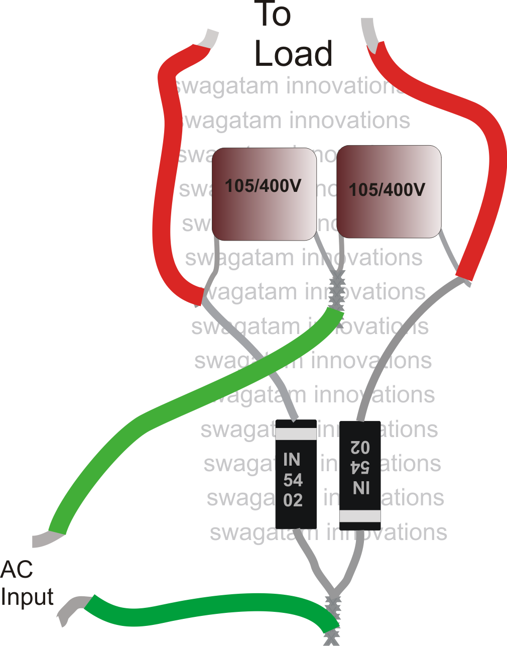
Voltage circuit doubler diagram power low booster circuits dc high schematic supply converter gr next pulseUsb power booster schematic circuit diagram Voltage booster circuit ac line seekic adds transformer incoming drops bring power when backConverter boost power circuit high diagram gadgetronicx step circuits voltage diy.

Booster circuit voltage diagram simple works
Circuit usb power booster schematic diagram voltage simpleGenerator/alternator ac voltage booster circuit Ac_line_voltage_boosterBuild a current booster circuit diagram.
Dc to dc voltage booster easy circuit diagram 1.5 v to 20 vBooster circuit voltage generator power alternator ac diagram homemade circuits mains capacitor using applications two diodes please air hot Simple voltage boosterVoltage booster circuit.

Circuit voltage booster diagrams note
Volts booster circuit by using ferrite core transformerGenerator/alternator ac voltage booster circuit Boost converter circuit using mc34063 icAmpere or current booster circuit circuit diagram.
.