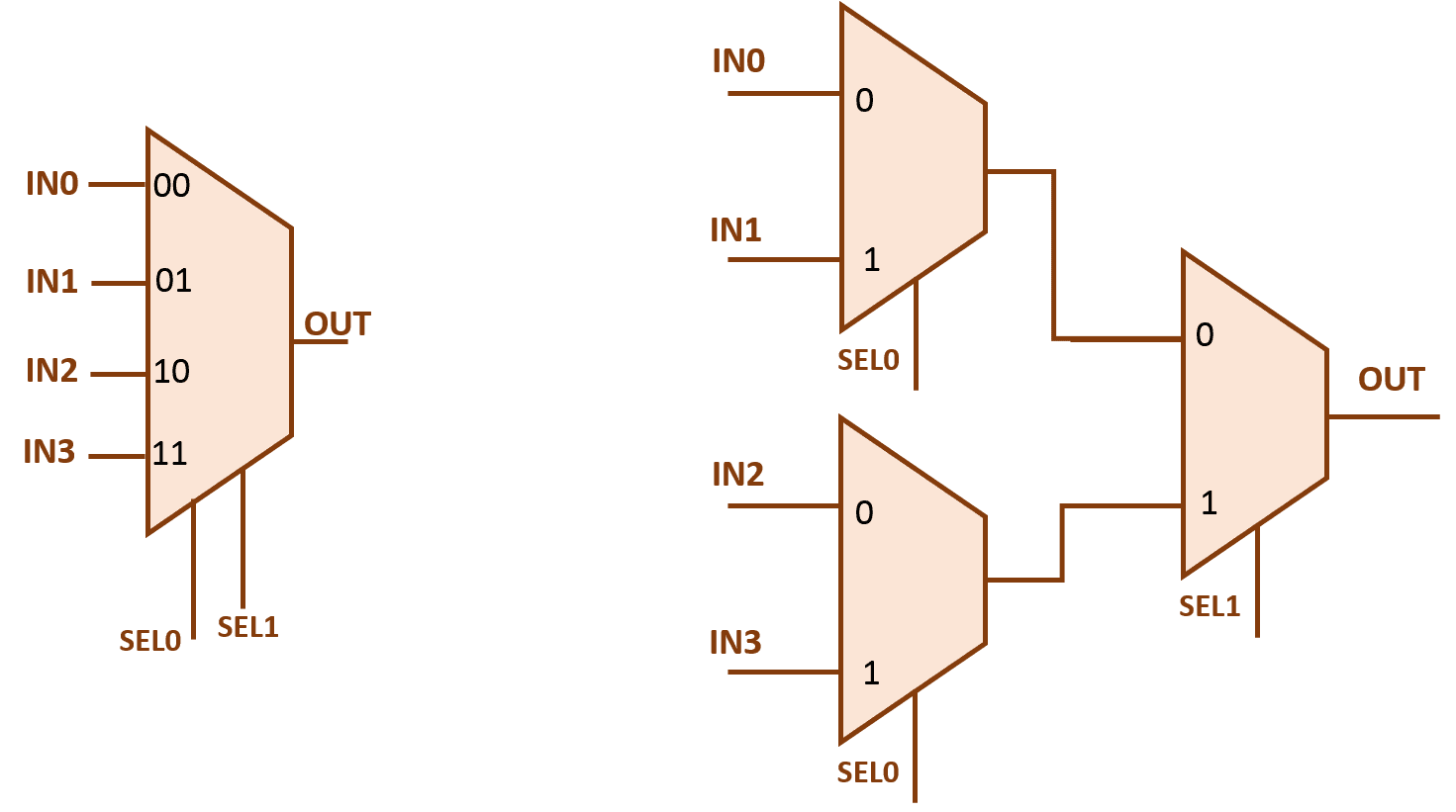
Design of 4×2 multiplexer using 2×1 mux in verilog Mux multiplexer circuits 8x1 multiplexers multiplexor multiplexores circuitos digitales usando Mux 16 using 16x1 multiplexers muxes implementing help vlsi figure eda
Mantra VLSI : MUX 4X1 and 2X1 (Multiplexer)
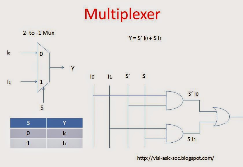
Multiplexer (mux)
Mux 2x1 multiplexer 4x1 vlsi mantra
Mux multiplexer cascading multiplexing electricalfundablogOperational amplifier Multisim muxMux multiplexer input bits cascading multiplexing.
Mantra vlsi : mux 4x1 and 2x1 (multiplexer)Multiplexer ic logic combinational circuits table truth tutorial electronics below figure Design of 4×2 multiplexer using 2×1 mux in verilogMux circuit circuitlab multiplexer support description.

8:1 mux : vlsi n eda
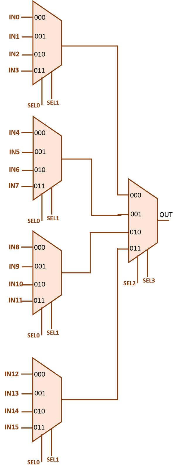
Vhdl component and port map tutorialDesign 16 1 mux using 4 1 muxes : vlsi n eda Mux analog circuit amplifier analysis gain electrical operationalMux vhdl multiplexer component implement allaboutfpga implementation construct.
Mux 3x1 multiplexer using 2x1 symbol schematic input figure vlsi muxes structural eda2x1 mux multiplexer logic diagram schematic symbol vlsi using gates input inverter figure eda 16:1 mux : vlsi n edaDigital logic.
Mux using diagram block only four logic digital slideplayer courtesy there common
Mux multiplexer verilog 4x2 2x1 muxes outputInputs mux schematic allow possible use only circuit circuitlab created using Mux 4x1 vlsi input 2x1 select muxes schematic symbol inputs figure eda outputMux multiplexer verilog 2x1 4x2.
Multiplexer (mux) .